Direct Answer: On shared motor control centers, VFD cabinets, and PLC panels exposed to overlapping water and electrical stress, crews must preserve panels untouched under lockout/tagout, document directional drip trails vs internal arc patterns, log fault-memory codes before reset, and hand evidence cleanly to licensed forensic investigators without making coverage or cause determinations.
.md twin for estimator QA and carrier file documentation.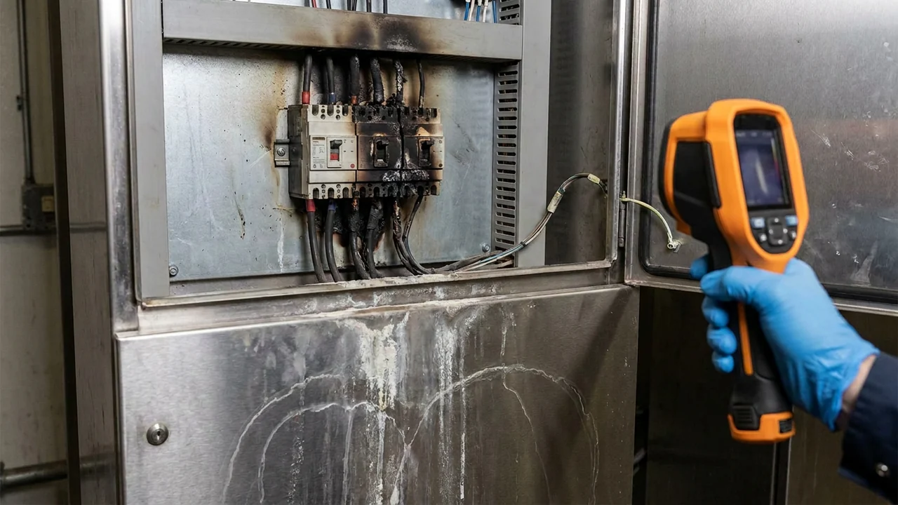
Commercial mechanical rooms, production lines, and rooftop-fed electrical closets rarely fail neatly. When a sprinkler head activates, a domestic riser bursts above an electrical room, or a storm knocks out utility phases while blowing rain through louver vents, shared motor control centers (MCCs), Variable Frequency Drives (VFDs), and PLC cabinets frequently display both moisture residue and scorched breakers or blown power boards.
That overlap triggers one of the sharpest investigative disputes in commercial claims: did direct water intrusion cause a conductive short inside the cabinet, or did an electrical surge, phase loss, or pre-existing loose lug generate localized arcing independent of water contact? Because property forms, electrical-disturbance exclusions, and equipment-breakdown endorsements treat water versus electrical causation differently—and because utility or contractor subrogation frequently hinges on the answer—cleaning or resetting a panel prematurely can destroy the entire forensic record.
Practical scope boundary (non-UPL, policy & subrogation disclaimer): Restoration technicians and contents estimators follow NFPA 921 evidence-preservation discipline and ANSI/IICRC S320 custody rules solely to stabilize safety, photograph untouched physical evidence, and route diagnostic facts. They do not render binding cause-and-origin opinions (reserved for licensed electrical engineers / certified investigators), interpret electrical exclusions, or make subrogation liability determinations.
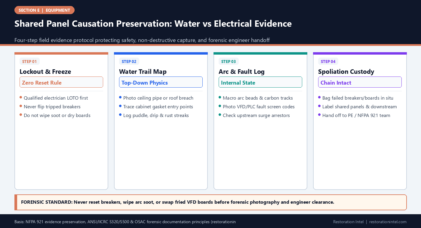
Shared Panel Causation Preservation: Water vs Electrical Evidence
Field Evidence Differentiation: Direct Water Intrusion vs Electrical Surge / Arcing Cues
Objective physical observations crews must capture cleanly—without drawing legal causation conclusions—before remediation or panel replacement.
| Observation Zone | Direct Water Contact Cues to Document | Electrical Surge / Arcing Cues to Document | Required Photo & Instrument Proof | Critical Field Preservation Rule |
|---|---|---|---|---|
| Enclosure Exterior & Conduit Entries | Overhead pipe drip stains, wet top knockouts, mineral streaks down door | Dry exterior cabinet; no ceiling water path or wet conduit hubs | Wide room + top-of-cabinet macro + thermal/moisture reading on drywall above | Photograph ceiling/conduit path before plumbers repair pipe or cap vents |
| Cabinet Interior & DIN Rails | Directional water pooling on floor pan, mineral deposits, uniform rust on screws | Localized carbon plume at one lug/phase, dry dust intact elsewhere | Straight-in panel overview + oblique macro showing dry dust vs wet streaks | Prohibit compressed-air blow-off or wipe-down prior to investigator arrival |
| Breakers, Contactors & Busbars | Green/white galvanic corrosion across wet copper/aluminum terminals | Melted copper beads, pitted contact faces, phase-to-phase blast marks | Glare-free macro of terminal numbers, wire insulation melt, & torque paint | Tag and bag failed breakers under spoliation hold if replaced for emergency power |
| VFDs, PLCs & Power Supplies | Watermarks on conformal coating, corrosion bridges under SMD chips | Blown MOVs, split surge capacitors, soot burst at incoming line rectifier | Serial plate + clear board macro + HMI/VFD fault-code readout before power cycle | Never energize damp drives to 'test'; capture non-volatile fault logs via OEM tech |
| Upstream Utility & Surge Arrestors | Clean utility meter/main gear outside wet room; intact surge indicator | Tripped SPD indicator flags, utility recloser event log, neighboring panel hits | Photo of main distribution SPD status LEDs + utility outage timestamp log | Record exact outage/re-energization timestamps from plant staff or BMS |
| Downstream Motors & Shared Loads | Waterlogged junction box at motor peckerhead or flooded floor pit | Burned stator windings on dry motor fed by same shared MCC bus | Megohmmeter log (by electrician) + junction-box interior photo + asset ID | Link every downstream motor ID back to its specific MCC bucket number |
Why Shared Motor and Control Panels Trigger Causation Disputes
In a commercial facility, a single Motor Control Center (MCC) or NEMA-rated control enclosure rarely serves just one isolated asset. One cabinet often houses the main disconnect, surge protective device (SPD), variable frequency drives, starter contactors, and PLC I/O racks controlling chillers, conveyor lines, exhaust fans, and pumps across multiple rooms. When water strikes an upper conduit penetration—or when a grid surge ripples through the building during a storm or fire-fighting shutoff—evidence of both water and electrical failure frequently sits inches apart inside the same steel box.
Under ANSI/IICRC S500 and corrosion-creep principles, conductive water bridging across energized 480V busbars can create violent secondary arcing that mimics a primary electrical surge. Conversely, a power-quality transient during utility restoration can blow MOVs and VFD rectifiers inside a damp room whose enclosure actually kept water out.
Because commercial property policies, electrical-arcing exclusions, and boiler-and-machinery / equipment-breakdown coverages divide responsibility based on proximate physical cause, guessing causation in the field or wiping away evidence during rapid emergency cleanup puts both the insured and the subrogation team at a severe disadvantage.
- Never assume cause from room wet state: Even in a flooded mechanical room, dry-inside vs wet-inside panel interiors must be proved photographically.
- Map the bucket-to-machine tree: Record which MCC bucket or breaker feeds each downstream motor, pump, or process skid.
- Escalate complex panels early: Flag multi-drive MCCs and high-voltage switchgear for licensed electrical engineer inspection on Day 1.
Life Safety First: LOTO, Arc-Flash Boundaries, and Untouched Evidence
Before any documentation camera approaches an electrical enclosure, life safety controls every step. Wet industrial panels, standing water on concrete floors, and carbon-tracked breakers carry extreme shock and arc-flash hazards. Contents and mitigation technicians must never open energized MCC doors, probe busbars, or touch tripped breakers—a licensed master electrician or qualified plant maintenance engineer must verify de-energization, apply Lockout/Tagout (LOTO), and test zero-energy state first.
Once the panel is verified safe and open, the golden forensic rule mirrors NFPA 921 and NIST OSAC forensic documentation principles: capture untouched reality before anyone touches a rag, Shop-Vac, or screwdriver. Do not vacuum carbon soot out of a VFD bay, do not blow moisture off terminal blocks with compressed air, and do not flip tripped breakers back on to see what runs.
Photographing untouched dust trails, dry salt lines, water droplets hanging from upper conduit locknuts, and localized soot cones creates the exact spatial evidence investigators need to reconstruct whether damage migrated downward from water or erupted outward from an internal arc.
- Zero-energy verification: Require qualified LOTO sign-off before opening panel doors or shooting internal close-ups.
- Zero wipe-down pre-photo: Document soot plumes, mineral streaks, and moisture droplets exactly as discovered prior to any stabilization.
- No ‘test-flipping’ breakers: Never reset tripped breakers or re-energize wet VFDs; resetting destroys fault state and risks secondary arc blasts.
Capturing Fault Logs, Drip Paths, and Panel-Level Evidence Sequence
Effective panel documentation follows an outside-in funnel that connects building context to component-level macro proof, building on forensic water-damage photography and diagnostic teardown protocols. Start above and behind the cabinet: shoot ceiling penetrations, sprinkler heads, roof leaks, and top-entry conduit hubs where water can travel down inside EMT or rigid pipe directly onto live lugs.
Next, shoot the entire open cabinet face straight-on so every bucket, breaker handle position (ON, OFF, or TRIPPED), and VFD keypad sits in one readable frame. Then capture angled macro shots of specific failure evidence: mineral rings around DIN rails, corroded green copper oxide, melted terminal lugs, ruptured electrolytic capacitors, or intact dry cobwebs sitting right beside a fried relay.
Crucially, if a PLC or VFD retains non-volatile fault-history logs—recording overvoltage, ground-fault, or phase-loss timestamps—have an OEM controls technician pull and export those logs before disconnecting backup batteries or swapping drives for emergency restart.
- Conduit-path check: Inspect inside top-entry conduit bushings and weatherheads; water frequently travels inside pipes while cabinet exteriors look dry.
- Handle-position archive: Photograph every breaker handle position clearly before electricians throw disconnects for temporary bypass.
- Fault-code export: Preserve VFD trip histories, BMS alarm logs, and power-quality meter timestamps with exact clock-offset notes.
Spoliation Holds, Temporary Bypass, and Forensic Engineer Handoff
Commercial plants cannot stay shut down for three weeks waiting for a joint lab exam if a temporary bypass panel can restore critical refrigeration or production safely. The solution is never throwing away failed components in the rush to restart—it is structured evidence preservation under spoliation-hold chain of custody.
Before an electrician pulls a burned VFD, ruptured surge arrestor, or corroded 400-amp main breaker to install a temporary replacement, record its exact cabinet slot, photograph all wiring terminations before landing leads are disconnected, tag each failed component with an indelible custody label, and seal it in an antistatic or vapor-protective evidence container with signed transfer logs. Also check subrogation escalation flags if a failed sprinkler coupling, contractor weld, or utility transformer event triggered the incident.
In the final packet, describe physical observations strictly in neutral, factual language (‘overhead sprinkler pipe wet above conduit hub; copper-bead arcing observed at Phase B terminal of Drive 2’) and explicitly leave proximate cause, coverage allocation, and subrogation liability to the licensed electrical engineer, adjuster, and counsel.
- Pre-removal wiring photos: Shoot clear wire-label photos on every terminal before electricians disconnect a failed drive or breaker for emergency swap.
- Dual-signed evidence bags: Place removed failed panels, MOVs, and breakers under locked custody rather than jobsite dumpsters.
- Neutral fact reporting: Report observed water paths, moisture readings, and arc locations objectively without declaring policy causation.
Practitioner Verification Checklist (E-13)
- Ensure a qualified electrician performs Lockout/Tagout (LOTO) and verifies zero energy before opening any wet or fire-exposed control cabinet.
- Enforce a strict zero-touch rule—never reset tripped breakers, wipe soot plumes, or blow-dry panels—until untouched forensic photos are complete.
- Document the full outside-in path: overhead piping/conduit entry points, open cabinet overview, breaker handle states, and macro water vs arc cues.
- Have an authorized controls technician export non-volatile VFD, PLC, and BMS fault-history timestamps before batteries or drives are disconnected.
- Tag, photograph pre-disconnection, and retain all removed failed breakers/drives under spoliation hold, with a non-UPL note routing causation/coverage to licensed investigators and adjusters.
Standards, Authority References & Related Reading
Primary standards, insurance definitions, and sibling Restoration Intel guides referenced in this brief:
- NFPA 921 Guide for Fire and Explosion Investigations
- ANSI/IICRC S320 Standard for Professional Contents Restoration
- ANSI/IICRC S500 Water Damage Standard
- IRMI Insurance Glossary: Subrogation
- NIST Organization of Scientific Area Committees for Forensic Science
- Related Guide: Diagnostic Testing and OEM Teardown Protocols: Proving Internal Smoke, Moisture, or Surge Damage
- Related Guide: Electronic Circuit Boards and Corrosion Creep: Why Wet or Soot-Exposed Machinery Fails Weeks After Loss
- Related Guide: Field Guide: Evidence Preservation & Spoliation-Hold Rules on Subrogation and Arson Investigations
- Related Guide: Field Guide: Subrogation & Manufacturer Defect Escalation Flags on Appliance-Origin Losses
- Related Guide: Clean & Grey Water (Cat 1–2) Pipe-Burst Losses: Damage Evidence & Forensic Photography Rules
- Related Guide: Structure Fire, Smoke & Protein-Residue Losses: Damage Evidence & Forensic Photography Rules
.md twin for desk QA and team training.Frequently Asked Questions
Why shouldn't technicians wipe soot or blow moisture out of a control cabinet before inspection?
Wiping carbon tracks or drying mineral drip lines erases the spatial clues forensic electrical engineers use to distinguish external water-induced tracking from internal surge or loose-connection arcing.
Can water entering a panel cause electrical arcing that looks like a power surge?
Yes. Conductive water bridging across energized busbars or drive terminals frequently triggers phase-to-phase arcing and blown components, which is why photographing overhead water entry paths and internal drip trails is essential.
What if a plant must swap a failed VFD or breaker immediately to resume operations?
Document the untouched unit in situ, capture wire labels prior to disconnection, export fault-history logs, and seal the removed failed part under a signed spoliation-hold custody log for joint forensic inspection.
Do restoration estimators determine whether water or electrical surge is the covered proximate cause?
No. Restoration crews document objective physical observations and preserve evidence. Formal cause-and-origin findings rest with licensed electrical engineers or certified investigators, and coverage determinations rest with the carrier adjuster and counsel.